Electric Motor Rotor Shaft Pressing Machine: Precision Press-Fitting & Quality Control
How do global electric motor manufacturers eliminate shaft runout, core delamination, and air-gap eccentricities during high-speed rotor assembly? Explore servo-hydraulic cold and thermal press-fitting technology engineered by Zunqi Intelligent Equipment Co., Ltd.
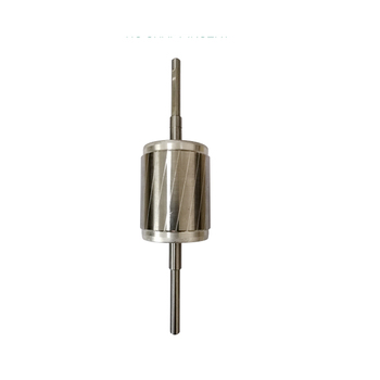
In electric motor mass production, the mechanical interface between the rotor shaft and the laminated silicon steel stack determines the electromagnetic balance, mechanical vibration, and operational lifespan of the entire motor assembly.
The Engineering Challenge
Modern high-efficiency induction motors, permanent magnet synchronous motors (PMSM), and brushless DC (BLDC) powertrains demand strict mechanical tolerances. Shaft-to-rotor bore interference fits typically range from 0.015 mm to 0.045 mm (k5, m5, and p6 tolerances). Inserting a hardened steel shaft through stacked lamination sheets creates significant localized shear stress.
Conventional hydraulic or manual toggle presses lack closed-loop displacement and load feedback. This creates critical failure risks: axial buckling of thin silicon steel laminations (0.20 mm - 0.35 mm electrical steel), micro-galling on the shaft journal seat, flaking of anti-rust coatings, and permanent shaft bending. A shaft deflection of just 0.008 mm Total Indicator Reading (TIR) produces uneven magnetic pull, severe cogging torque, abnormal bearing chatter, and premature motor failure.
To overcome these structural risks, modern motor production facilities deploy automated electric motor rotor shaft pressing machines equipped with dynamic load-displacement signature analysis (P-S curve monitoring), ensuring repeatable alignment, strict perpendicularity, and consistent axial stack compression.
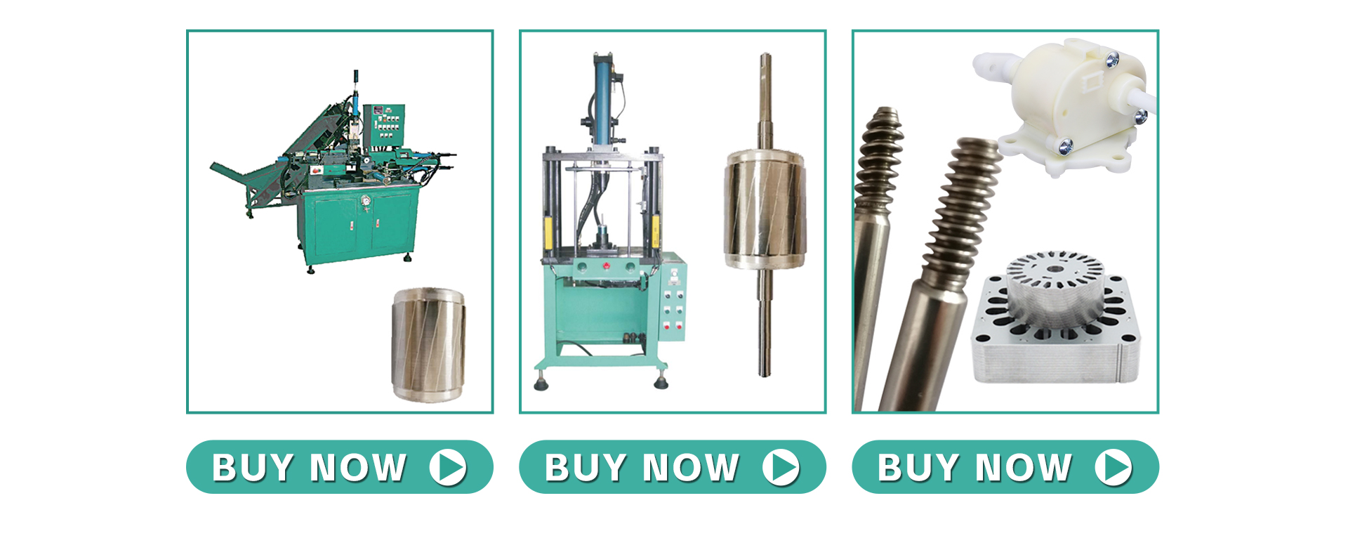
Zunqi Intelligent Equipment Co., Ltd. configures cold press, servo-electric, and integrated thermal shaft assembly systems matched to your motor frame dimensions, cycle targets, and factory power specifications.
Servo-Electric
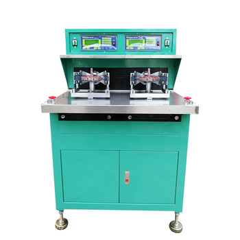
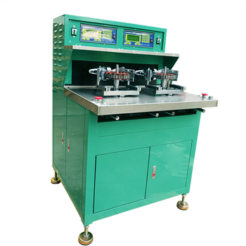
High-Precision Servo Rotor Shaft Pressing Machine
Equipped with an electric planetary roller screw and high-resolution optical encoder for sub-micron positional repeatability. Features real-time P-S curve monitoring to reject misaligned shafts instantly.
Integrates auto-loading hopper for motor shafts, induction heating pre-station, servo press insertion station, and post-assembly runout verification probe into a unified cell.
Cycle Time: 6 – 10 seconds per finished rotor
Integrated LVDT dial indicator for 100% TIR runout audit
Automated good/reject sorting chute mechanism
Compatible with automated factory AGV and robot arms
As electric motor manufacturing shifts toward hairpin windings, high-density permanent magnet rotors, and ultra-quiet residential appliances, procurement requirements for shaft pressing equipment are changing significantly.
Key Trends Transforming Rotor Assembly
1. Transition from Unmonitored Hydraulic to Closed-Loop Servo Actuation: Hydraulic press systems have dominated motor manufacturing for decades due to their raw force density and lower initial purchase cost. However, hydraulic systems suffer from thermal oil viscosity drift, seal wear, noisy hydraulic pumps, and lack of fine position control. Leading global motor suppliers are rapidly switching to servo-electric presses. Servo presses offer clean-room cleanliness, 75% lower electrical power consumption, and programmable multi-stage pressing profiles (rapid approach, gentle insertion deceleration, and micro-dwell at the mechanical shoulder).
2. Adoption of Force vs. Displacement Signature Analysis (Envelope QC): With tier-one automotive and premium appliance clients demanding zero-defect tolerance (PPM < 10), modern rotor shaft pressing machines must provide complete curve envelope verification. By monitoring the exact insertion force across every 0.01 mm of stroke, the system detects irregularities—such as lead-in chamfer burrs, bore ovality, missing keyways, material hardness anomalies, or sheared lamination teeth—rejection happens mid-stroke before costly downstream processing occurs.
3. Rise of Thermal Induction Pre-Expansion Cells: For EV traction motors and multi-pole high-torque rotors, heavy cold interference fits (> 0.050 mm) risk scoring the internal permanent magnets or buckling laminated silicon sheets. The latest procurement trend pairs an intermediate medium-frequency induction heater that expands the rotor core bore by 80°C – 120°C directly before a zero-force or low-thrust shaft drop-in, eliminating mechanical galling entirely.
4. Digital Traceability & MES Cloud Interfacing: Factory MES networks require full traceability for every individual motor rotor produced. Zunqi machines interface seamlessly with factory networks via OPC-UA, Modbus TCP, and Ethernet/IP protocols, transmitting peak force, seating position, runout reading, cycle timestamp, and operator IDs automatically.
Servo systems consume electric power strictly during the downward pressing stroke, eliminating continuous idling motor draw from traditional hydraulic oil pumps.
02
Tooling Longevity
Guided linear bushings and carbide-tipped push mandrels prevent off-center side loading, extending fixture life well beyond 2,500,000 continuous assembly cycles.
03
Sub-10s Cycle Times
Synchronized rapid-feed pneumatic nesting mechanisms and high-speed servo actuators reduce average shaft press cycle times to just 6 to 10 seconds.
04
Rapid Changeover
Save over 100 rotor recipes in the PLC touch-screen display with quick-clamp pneumatic tooling to complete core changeover in under 10 minutes.
Manufacturing Discipline
Zunqi Quality Control & Machine Build Workflow
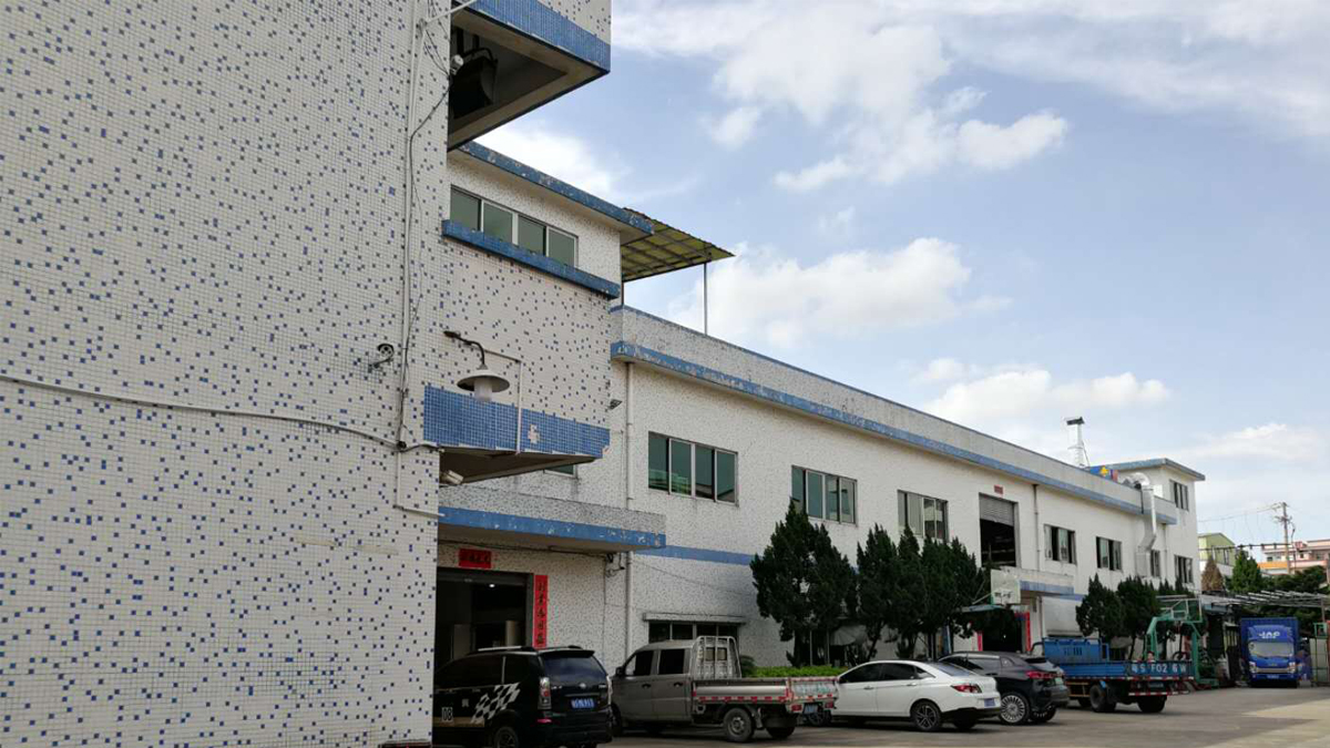
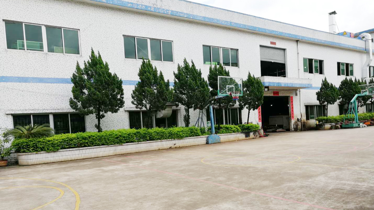
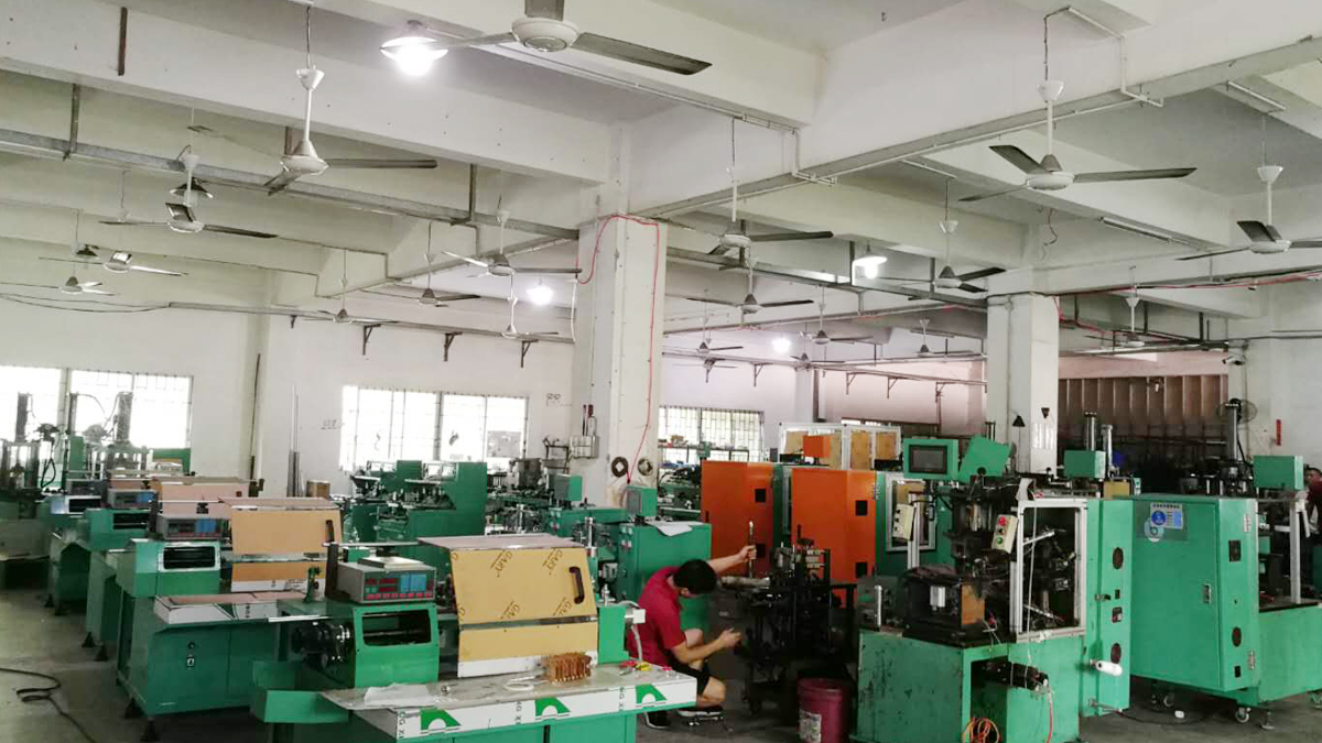
Every electric motor rotor shaft pressing machine undergoes stringent design, machining, electrical assembly, and prototype trial testing within our Dongguan production facility.
STEP 01
Drawing & Fit Analysis
We analyze shaft journal limits, interference fits, stack heights, and core laminations to calculate exact required press tonnage.
STEP 02
Precision Fixture CAD
Custom mandrels, guide bushings, and bottom support anvils are modeled with finite element deflection analysis.
STEP 03
Frame Machining
Machine beds, guide columns, and pressing platens undergo stress relief heat treatment and precision surface grinding.
STEP 04
PLC & Sensor Wiring
Integration of high-speed PLCs, servo amplifiers, multi-axis motion cards, and calibrated piezoelectric load cells.
STEP 05
Mechanical Alignment
Ram perpendicularity and table parallelism are adjusted and dial-checked to within 0.015 mm across full travel stroke.
STEP 06
Sample Trial Pressing
Customer-supplied rotor cores and shafts are test-pressed; force curves and TIR shaft runout are measured and logged.
STEP 07
FAT & Video Approval
Full 48-hour continuous cycle endurance testing, safety audit, and video acceptance shared directly with the buyer.
Integrating the Shaft Press in Full Motor Assembly
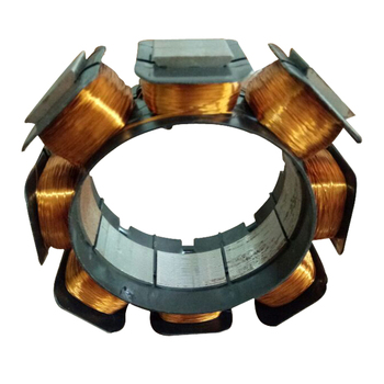
A high-performance motor line synchronizes stator manufacturing, rotor stacking, precision shaft assembly, and finish turning into a seamless, high-yield operation.
Rated voltage, test frequency, insulation resistance (MΩ)
Engineering Integration Tip: When sending rotor drawings, specify both cold interference fit tolerances and whether knurled or smooth shaft journals are used, allowing our engineers to optimize ram acceleration profiles and guide anvil fixtures.
Buyer Knowledge Base
Frequently Asked Questions: Rotor Shaft Pressing
Direct technical answers to questions commonly queried by motor design engineers, plant procurement directors, and automation system integrators.
How do servo-electric rotor shaft pressing machines prevent lamination core delamination?
Servo-driven shaft pressing machines utilize real-time load cell feedback and micron-precision displacement encoders to construct dynamic force-distance curves (P-S signature curves). If resistance spikes abruptly due to burrs, micro-galling, or angular misalignment, the servo drive decelerates or halts in milliseconds before mechanical yield thresholds are exceeded. This closed-loop control prevents lamination separation, buckling, and shearing of the core clamping rivets, ensuring optimal magnetic properties across the stack.
What interference fit tolerances are compatible with automatic rotor shaft pressing?
Industrial cold interference pressing typically accommodates shaft-to-bore diametrical interference fits between 0.015 mm and 0.045 mm (e.g., k5, m5, or p6 fit classes). Tighter interferences often incorporate precision chamfer guides, molybdenum disulfide anti-seize micro-dosing, or thermal assembly assistance (induction heating) to eliminate galling while maintaining firm rotational lockup.
Can one rotor shaft pressing machine accommodate multiple motor frame sizes?
Yes. Zunqi designs multi-model adaptable fixtures featuring quick-change tooling nests, digital micrometric backstops, and programmable servo travel profiles stored in recipes within the touch-screen HMI. Changeovers between varying shaft lengths, stack heights, and journal diameters typically take under 10 minutes without requiring manual hydraulic readjustment.
How does shaft insertion accuracy influence motor noise, vibration, and harshness (NVH)?
Improper insertion force or slight angular runout introduces residual axial bending stress into the motor shaft, resulting in total indicator reading (TIR) runout greater than 0.008 mm. This directly impairs concentricity within the stator bore, causing uneven electromagnetic air-gap flux, localized magnetic saturation, higher parasitic cogging torque, and severe acoustic resonance at operational speeds.
What verification and acceptance testing is conducted prior to machine dispatch?
At Zunqi Intelligent Equipment Co., Ltd., every machine undergoes full FAT (Factory Acceptance Testing) using the customer's actual rotor cores and shafts. We verify press force calibration, stroke repeatability (±0.01 mm), shaft end runout via dial indicator analysis, cycle time under load, and provide continuous 48-hour endurance test verification along with high-definition inspection video records before packing.
What power supply and factory utilities are required for installation?
Standard installations run on 380V/415V 3-phase 50/60 Hz power, while compact benchtop servo models can operate on 220V single-phase supplies. A clean pneumatic shop air line (0.5 – 0.7 MPa) is required for pneumatic safety guards, automated clamping cylinders, and parts ejection slides.
How does Zunqi provide after-sales engineering and technical commissioning abroad?
All machines include complete English technical manuals, electrical schematics, and interactive video setup walkthroughs. Our Dongguan engineering team provides prompt remote video commissioning via team video link (response time under 9 hours). For turnkey motor production lines, our field service engineers can travel on-site for comprehensive line commissioning and operator training.
Zunqi Intelligent Equipment Co., Ltd. is a specialized motor manufacturing equipment builder located in Qishi Town, Dongguan City, Guangdong Province, China. For 17 continuous years, our engineering team has designed, assembled, and exported precision stator and rotor automated machinery to motor factories across the globe.
Company Name
Zunqi Intelligent Equipment Co., Ltd.
Location
Dongguan, Guangdong, China
Industry Experience
17 Continuous Years
Total Employees
51 – 100 Dedicated Personnel
Annual Export Revenue
US$2.5 Million – US$5 Million
Average Response Time
≤ 9 Hours
Why Engineering Buyers Partner With Zunqi
Custom Tooling Ground to Exact Rotor Drawings: We do not offer generic presses; every press arbor, clamping collet, and locating anvil is machined to match your rotor core and shaft dimensions.
World-Class Industrial Component Partners: Configure your machine control systems using internationally supported brands—such as Siemens, Mitsubishi, Schneider, Omron, Delta, Inovance, SMC, and Airtac—for seamless local plant integration.
Guaranteed After-Sales Peace of Mind: Comprehensive 1-year machinery warranty, free lifetime remote video support, and fast dispatch of wearing parts and custom tooling.
Send your motor rotor drawings, stack lengths, and shaft fit tolerances to [email protected]. Our senior technical application engineers provide comprehensive tooling proposals and cycle time calculations within 9 hours.