Engineered Stator Winding & Insertion Machinery
Explore precision-tooled machinery engineered for BLDC motors, induction drives, ceiling fans, table fans, water pumps, and industrial compressors. Custom-machined tooling built to your exact lamination and stator blueprints.
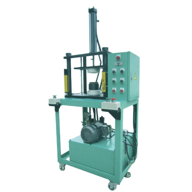
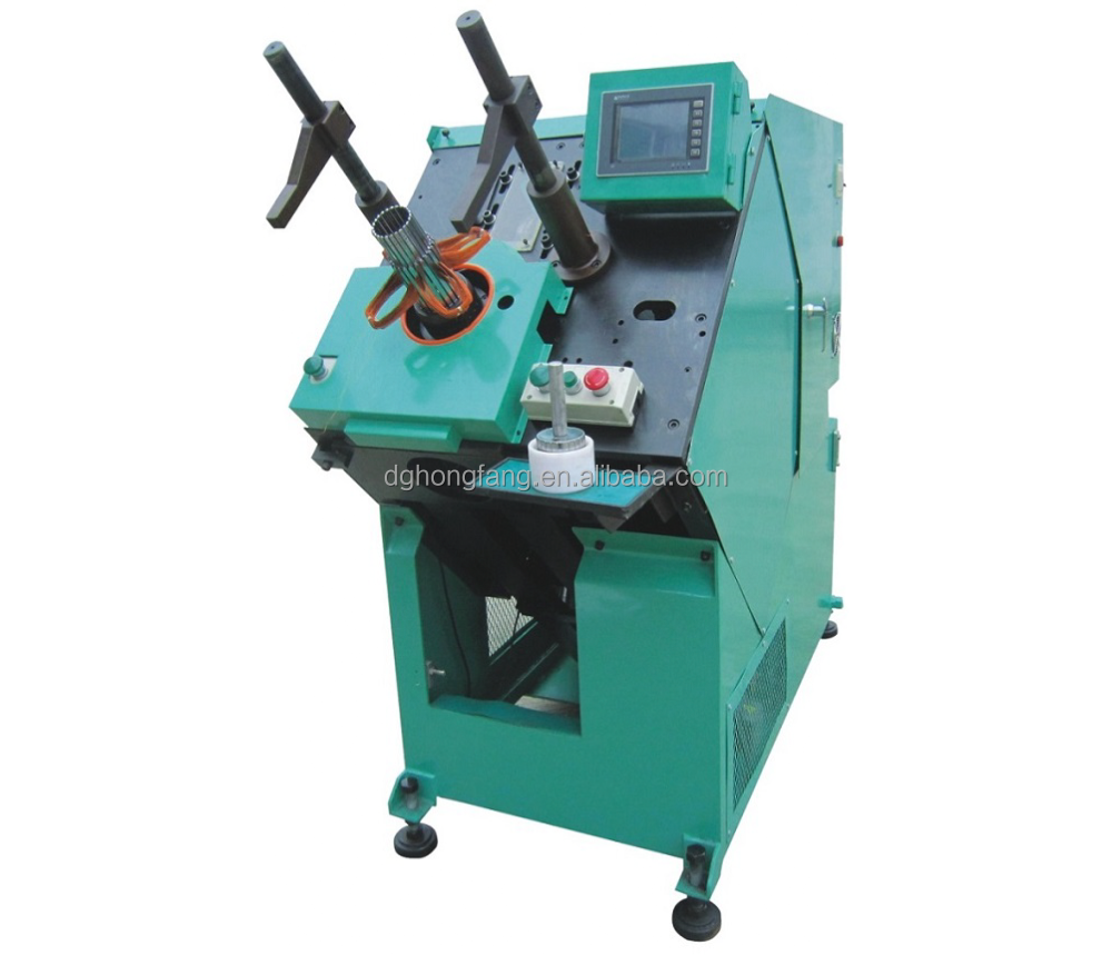
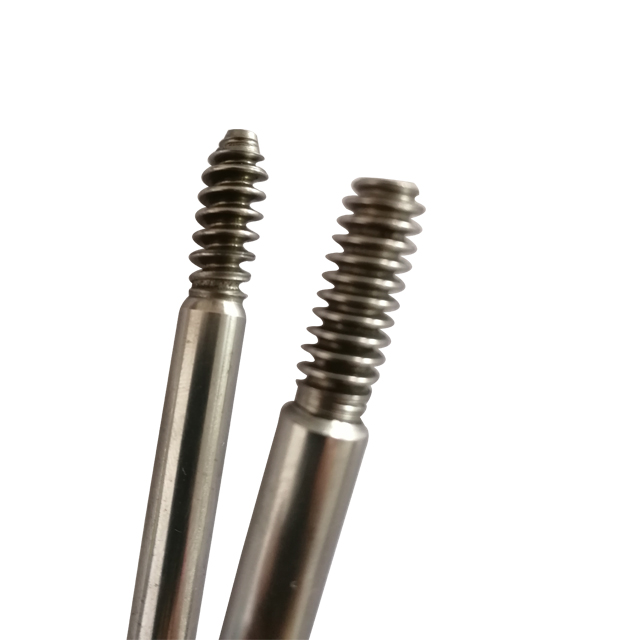
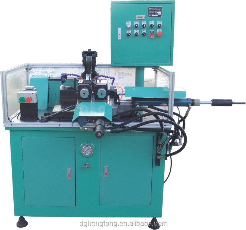
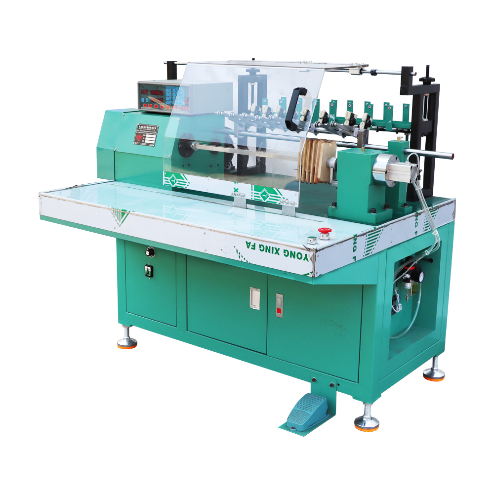
Engineering Anatomy of Automatic Stator Coil & Wedge Insertion
In high-efficiency induction motor and permanent magnet synchronous motor (PMSM) manufacturing, the coil and wedge insertion phase constitutes the most mechanically demanding bottleneck. Unlike manual winding placement—which suffers from erratic slot-fill density, inconsistent end-turn flare, and micro-fractures in enamelled insulation layers—modern automatic stator coil and wedge inserting machines execute synchronized mechanical insertion in a singular, servo-governed kinematic stroke.
The insertion mechanism operates via an assembly of hardened alloy tooling blades arranged circular to match the internal stator bore diameter (ID). The pre-wound coil groups—transferred from automated multi-spindle winders (such as 8-head CNC units)—rest within transfer tooling fixtures. Simultaneously, slot insulation wedges (fabricated from DMD, Nomex, polyester film, or vulcanized fiber) are fed from continuous coil stock, scored, cut to precise stack-length tolerances, and formed into specialized trapezoidal or curved profiles.
Synchronous Multi-Axis Servo Control
Replaces pneumatic and fixed-mechanical linkages with closed-loop servo drives. Push rods accelerate and decelerate smoothly across variable stack heights, eliminating wire snap caused by abrupt mechanical thrusts.
Damage-Free Wire Guiding Blades
Tooling guide blades undergo vacuum quenching and mirror-finishing (Ra < 0.1μm), ensuring high-density enameled copper or grade-EC aluminum wire enters narrow slot openings without coating delamination.
Continuous Wedge Feed & Sizing
Integrates servo-fed insulation paper roll stock with in-line rotary cutting. Precise feed lengths prevent wedge overshoot, preventing interference with rotor insertion while securing slot ground integrity.
Turnkey Stator Production Line Sequence
A production-ready stator line balances cycle times across every station. Below is the benchmark engineering flow from raw core lamination to finished, balanced electric motor rotor.
| Stage | Process Operation | Primary Equipment | Critical Engineering Parameters | Quality Checkpoint |
|---|---|---|---|---|
| 01 | Slot Cell Insulation | Auto Slot Paper Inserting Machine | Paper cuff width, fold depth, lamination stack indexing | Dielectric withstand > 2500V, edge creepage clearance |
| 02 | Primary Coil Winding | CNC Multi-Head Auto Winder (HF-R22 / 8 Heads) | Flyer RPM (up to 3000), tension control, wire gauge 0.1-1.2mm | Turns accuracy ±0 turns, resistance balance < 1% deviation |
| 03 | Coil & Wedge Insertion | Servo Coil & Wedge Inserting Machine | Pushing force curve, blade taper tolerance, wedge length | Zero wire peel, wedge protrusion < 0.5mm, ground fault check |
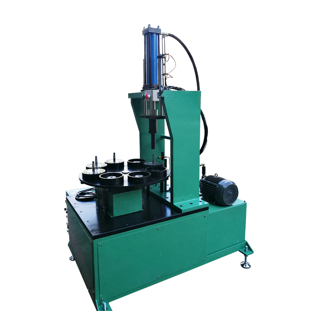
| 04 | Intermediate Forming | Stator Coil Intermediate Shaping Machine | Hydraulic expansion pressure, axial stroke depth | Bore clearance clearance confirmation, end-turn spread |
| 05 | End-Turn Lacing | Servo Double-Side Coil Lacing Machine | Cord tension, stitch pitch (slot-by-slot or interval) | Vibration test resistance, tight wire bundle retention |
| 06 | Final Coil Forming | HF-W120H Final Coil Shaping Machine | 3-direction hydraulic press: inner bore, end face, outer flare | Overall stator height & OD envelope conformity to housing |
| 07 | Rotor Surface Turning | HF-C60 Rotor Lathe & Surface Cutter | Cutting feed rate, aluminum smear suppression, concentricity | Uniform electromagnetic air gap tolerance (< 0.02mm) |
| 08 | Rotor Shaft Pressing | Hydraulic Stator/Rotor Shaft Press | Interference fit tonnage, axial positioning stopper | Shaft runout < 0.015mm, push-out retention force |
Future Procurement Trends in Motor Manufacturing Machinery
As international energy efficiency standards tighten (IE3, IE4, and IE5 regulations) and electrification expands from EV powertrains to industrial compressors, smart HVAC systems, and BLDC residential appliances, procurement strategies are undergoing massive structural shifts.
Higher Slot-Fill Demands
OEM buyers require machine tooling capable of handling denser slot-fill factors (upwards of 78% in copper distributed stators). Insertion blades and push fingers must incorporate ultra-thin, high-hardness alloy geometries to avoid slot pinch.
Rapid Tooling Changeover (SMED)
Single-Minute Exchange of Dies (SMED) is dominating factory requirements. Modern manufacturers transition between different stator ODs, IDs, and stack heights in under 20 minutes through modular quick-lock tooling cartridges.
Dual Copper & Aluminum Capability
Due to volatile raw copper prices, motor plants in South Asia, Latin America, and the Middle East require coil inserting machines that seamlessly alternate between copper and EC-grade aluminum magnet wire without wire snapping.
IoT Telemetry & In-Line Inspection
Procurement teams demand integrated optical sensors and load-cell monitors that trace insertion force signatures. Any irregular pressure spike (indicating jammed wire or folded paper) halts the machine instantaneously before scrap occurs.
Technology Shift: Distributed Winding vs. Hairpin Segmented Pin Systems
While the automotive EV sector has witnessed a surge in rectangular copper hairpin winding lines, industrial motor, pump, HVAC compressor, and home-appliance sectors remain heavily reliant on distributed round-wire stator winding and insertion. The capital expenditure (CapEx) of a distributed insertion line is roughly 10% to 15% that of a high-power EV hairpin line, offering drastically superior flexibility across varying slot geometries, shorter production runs, and multi-voltage applications.
Furthermore, technological advances developed by China's leading machine exporters now allow round-wire insertion lines to achieve slot-fill ratios that rival segmented stators, without requiring expensive laser stripping, CNC twisting, or high-energy welding stations.
Why Tier-1 Motor Manufacturers Source from Zunqi / Hongfang
Headquartered in Qishi Town, Dongguan—at the epicenter of South China's electric machinery manufacturing cluster—Zunqi Intelligent Equipment Co., Ltd. delivers direct factory engineering, transparent credit history, and tailor-made tooling solutions.
17+ Years Export Track Record
Continuous verified exporter on global trade platforms with verified on-site facility audits. We operate dedicated CNC machining, electrical assembly, and trial-run inspection workshops in Dongguan, Guangdong.
100% Pre-Shipment Sample Trial
We do not ship based on theoretical drawings alone. Customers provide physical stator core and wire samples; we complete full tooling commissioning and deliver high-definition testing videos verifying cycle time, slot fill, and resistance.
Unified Line Tooling Synchronization
Eliminate inter-supplier finger-pointing. We design and synchronize the entire operational train: slot cell paper insertion, 8-head coil winding, servo coil/wedge insertion, dual-head intermediate and final forming, and double-side lacing.
Standardized Industrial Control Architecture (Configurable to Your Plant Specification)
Our control cabinets are engineered for effortless maintenance. We configure PLCs, servo drivers, touch HMIs, and pneumatic valves based on your facility's standardized spare parts inventory.
Frequently Asked Questions on Motor Insertion Machinery Procurement
Direct technical answers addressing factory floor implementation, electrical adaptation, wire compatibility, and custom tooling parameters.
What specific engineering parameters are required to build custom inserting tooling?
To precision-machine the insertion blades, push fingers, and wedge guides, we require: (1) 2D/3D stator lamination drawings showing slot dimensions, slot mouth opening width, internal bore diameter (ID), and external diameter (OD); (2) minimum and maximum stack height; (3) magnet wire specifications including diameter (mm or AWG), conductor material (copper or aluminum), and insulation grade; (4) winding diagram with turns-per-coil count and coil pitch; (5) wedge insulation material type and thickness.
How does the machine avoid damaging enamelled wire insulation during the insertion stroke?
Wire coating damage is prevented by a three-tiered mechanism: First, our insertion blades are fabricated from high-grade alloy tool steel, heat-treated to HRC 60–62, and polished to a mirror finish (Ra < 0.1μm) to minimize frictional resistance. Second, the tooling teeth expand outward slightly upon entering the bore, acting as physical shields that keep the copper wires from contacting the sharp silicon steel lamination teeth. Third, the servo motor executes a programmable velocity profile, ramping down speed at the exact point of wedge entry to eliminate impact stress.
Can a single inserting machine handle multiple stator models?
Yes. If the different stator models share the identical internal diameter (ID) and slot count, you only need to adjust the machine's stack height stroke electronically via the touchscreen interface (taking less than 2 minutes). If the stator models have different IDs, slot counts, or slot geometries, the entire tooling cartridge (blades, push rod, wedge magazine) can be interchanged. Our modular tooling interface enables complete mechanical changeover in under 20 to 30 minutes.
Can the equipment run on our factory's local voltage and frequency?
Absolutely. While standard internal control circuits run on 24V DC and single-phase 220V AC, we regularly build custom main electrical panels configured for 3-phase 380V (50Hz/60Hz), 415V, 440V, 480V, or 208V/220V depending on your plant's geographic location (e.g., North America, South America, Europe, Southeast Asia, or Middle East). Confirm your local factory three-phase supply when requesting your quote.
What is the delivery timeline, export packing standard, and warranty coverage?
Standard lead time for tooling-customized machinery is typically 25 to 35 working days from drawing sign-off and receipt of stator samples. For international shipment, all precision machined surfaces are coated with industrial anti-rust oil, vacuum-sealed in moisture-proof VCI film, bolted down to heavy-duty structural steel skid mounts, and encased in ISPM-15 compliant fumigation-free solid plywood sea freight crates. Every machine includes a 1-year comprehensive mechanical & electrical warranty, supported by lifetime technical support and fast-turnaround spare parts airfreight.
Request a Precision Stator Line Proposal
Send your stator core drawings, wire diameter, and target hourly output. Our senior mechanical engineers will generate an equipment layout, tooling calculation, and transparent FOB/CIF quote within 9 working hours.
