Advanced Industrial Automation for Electric Stator & Rotor Production
As the global demand for high-efficiency electric motors escalates across automotive, HVAC, home appliances, and renewable energy sectors, electric machinery original equipment manufacturers (OEMs) demand superior winding accuracy, shorter cycle times, and deterministic slot fill factors. This engineering dossier provides an in-depth exploration of rotor winding topologies, mechanical stress mitigation, thermal equilibrium inside the slot, and modern multi-axis programmable logic controller (PLC) architecture.
17+
Years Global Exporting
±0.005mm
Turning Precision Standard
85%+
Target Slot Fill Capacity
≤9 Hours
Engineering Response SLA
Engineered Machinery Portfolio
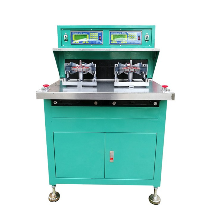
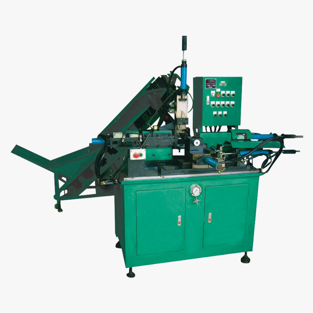
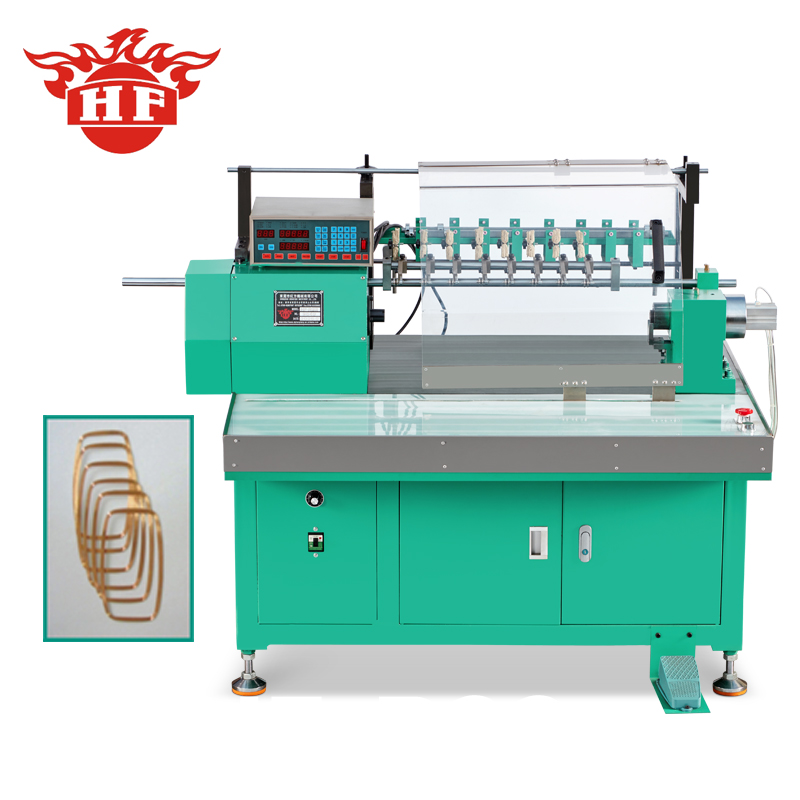
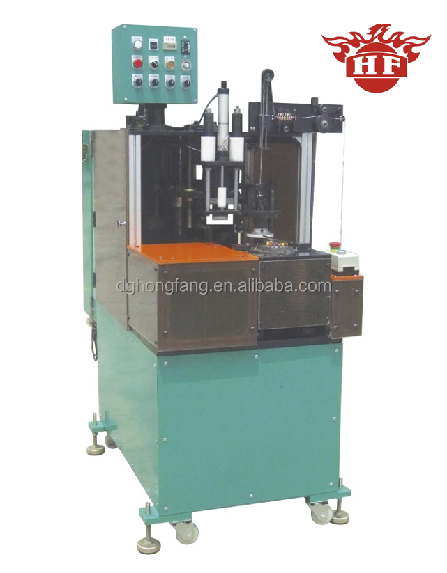
Featured Automated Winding & Rotor Processing Units
Factory-direct automation equipment engineered in Dongguan, China, completely adaptable with custom mandrels, tooling heads, and automated loaders.
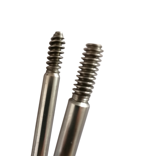
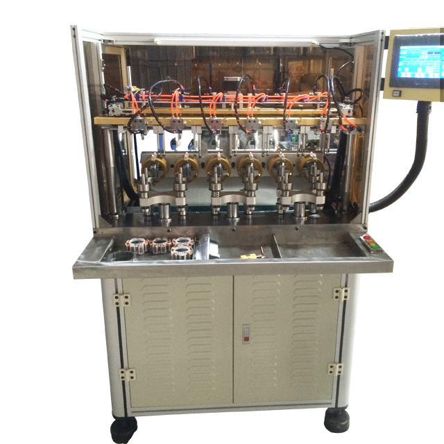
Principles of High-Speed Rotor & Stator Coil Placement
Rotor winding machinery—particularly for brushless DC (BLDC) motors, universal series-wound armatures, and ceiling fan outrunners—requires an exact balance between mechanical wire tension and flyer centrifugal acceleration. When winding fine enamelled copper or aluminum conductor wire (ranging from Ø0.10 mm to Ø1.20 mm), improper deceleration curves can compromise the polyimide-imide dielectric insulation film, introducing microscopic pinholes that manifest later as intra-turn dielectric breakdowns.
At Zunqi Intelligent Equipment, our multi-axis CNC flyer winders and needle winding platforms utilize closed-loop digital magnetic tensioners linked via industrial fieldbus protocols (EtherCAT or CANopen) directly to the servo drive amplifier. As the flyer velocity cycles from zero to 3,500 RPM within millisecond ramp windows, the active tension brake continuously dampens oscillatory whip. This guarantees that copper stretch factors remain strictly below 1.5%, preventing wire necking, electrical cross-sectional degradation, and excessive ohmic resistance variations across coil phases.
Strategic Sourcing Intelligence
Future Procurement Trends in Automated Motor Production
Procurement managers and process engineers must adapt to evolving geopolitical supply networks, high-efficiency regulations, and modular assembly methodologies.
Needle Winding Over Flyer Winding
For internal slot BLDC and permanent magnet synchronous motors (PMSM), procurement is shifting heavily toward multi-axis CNC needle winders. Needle winding achieves slot fill ratios exceeding 78% compared to traditional flyer methods, drastically diminishing copper losses and allowing thermal thresholds compliant with IE4 and IE5 standards.
Integrated Quality Analytics (In-Situ Testing)
Modern global contracts now mandate inline diagnostic verification. Automated cells now weave coil winding together with in-situ DC resistance checking, high-potential (Hi-Pot) surge tests, and partial discharge analytics immediately prior to pallet transfer, dropping scrap rates to fewer than 50 PPM.
Rapid Tooling Changeover (SMED Compliance)
With batch volumes becoming smaller and motor variants multiplying, high-value purchasers demand Single-Minute Exchange of Die (SMED) compliance. Modern rotor winders feature quick-release modular mandrels and universal recipe recall on HMI panels, reducing changeover periods from hours to under 15 minutes.
Technological Evolution: Mechanical vs. Direct-Drive Servo Winders
Historical winding machinery depended upon complex cam transmissions, gears, and timing belts. While robust, mechanical synchronizers suffered from mechanical backlash, gear backlash vibration, and significant tool wear. The new generation of custom OEM rotor winding machinery embraces direct-drive rotary torque motors and absolute optical encoder feedback.
| Engineering Attribute | Legacy Mechanical Cam Systems | Zunqi Servo-Electric CNC Platforms | Direct Operational Advantage |
|---|---|---|---|
| Tension Variance at Peak Velocity | ± 18.5% | ± 2.2% Closed-Loop Control | Zero copper necking, uniform layer resistance |
| Slot Fill Factor Limit | 60% – 66% | Up to 82% – 86% | Superior magnetic flux density, smaller motor footprint |
| Acoustic Emission Level | > 82 dBA | < 68 dBA | Enhanced plant ergonomic compliance (ISO 14001) |
| Tooling Changeover Duration | 120 – 180 Minutes | 12 – 15 Minutes Quick-Swap | Drastic reduction in idle cell labor cost |
| Maintenance Cycle Interval | Every 1,500 Operating Hours | Every 6,000 Operating Hours | Over 70% decrease in preventive downtime |
Why Global Tier-1 Manufacturers Partner With Us
Engineering Rigor, In-House Tooling & Turnkey Supply
Based in Qishi Town, Dongguan, Zunqi Intelligent Equipment integrates core industrial machine design with end-to-end motor assembly lines.
Tailored Tooling to Your Stator Geometry
We do not deliver off-the-shelf compromises. Every coil former, inserting blade array, wedge pusher, and expander shoe is custom-machined via slow-feeding CNC wire-cut EDM and high-speed CNC milling to your precise motor lamination drawing.
Standardized Industrial Architecture
Local maintainability is essential for export operations. We integrate international brands including Siemens, Mitsubishi, Omron, Delta, Inovance, SMC, and Airtac. Your maintenance technicians never struggle with proprietary, unserviceable components.
Full Line Synchronization
Beyond solitary winding stations, Zunqi engineers matched upstream and downstream sequences: slot insulation paper insertion, coil winding, simultaneous coil & wedge insertion, intermediate forming, double-sided servo lacing, rotor turning, and shaft pressing.
Engineering FAQ
Procurement & Technical Questions Answered
Detailed technical responses to clarify mechanical limits, tooling customization, electrical compatibility, and post-delivery acceptance.
What engineering documentation is required to fabricate custom winding tooling?
To produce custom formers, flyer shields, or inserting blade tooling, we require: (1) 2D and 3D CAD files (.DXF, .DWG, .STEP) of the bare lamination stack; (2) Finished stator/rotor assembly dimensions including slot liner thickness; (3) Conductor enamel specifications (copper or aluminum), wire diameter range, and turn count per coil group; (4) Coil head maximum height limits to ensure housing clearance. If drawings are confidential or incomplete, providing 3-5 physical sample laminations allows our Metrology Lab to perform optical CMM profiling.
How does the machine prevent wire scraping during high-speed insertion?
Our combined coil and wedge inserting machines utilize titanium-nitride-coated (TiN) guide blades ground to sub-micron surface finishes (Ra < 0.2 µm). During the vertical insertion stroke, pneumatic or servo pushers synchronize the entry of the coil bundle and the pre-formed insulation wedge simultaneously. By matching the blade clearance exactly to the stator tooth width, the conductor turns are guided into the slot without scrubbing against the sharp silicon steel edge, completely eliminating insulation peel.
Can a single rotor turning machine accommodate multiple shaft diameters and stack lengths?
Yes. Our HF-C60 and fine-turning series feature pneumatic collet chucks and adjustable tailstock centers with digital micro-metric readouts. The dynamic cutting travel, spindle RPM, and pass depths are programmable via the touchscreen HMI recipes. Mechanical adjustment between fan motor rotors with stack heights of 10 mm to 60 mm takes less than 10 minutes without exchanging the main pneumatic clamping assembly.
What electrical configurations are available for international export?
While standard bench winders run on single-phase 220V AC (50/60 Hz), heavy industrial multi-station lines, rotor turning lathes, and double-sided lacing machines are wired to three-phase 380V/415V/480V systems based on destination regional standards. We integrate CE-certified industrial transformers, line noise filters, and emergency-stop circuit relays conforming to EN ISO 13849-1 safety levels.
What is the Factory Acceptance Testing (FAT) protocol prior to export crating?
Every equipment build undergoes an intensive 72-hour burn-in trial. We request customer wire and lamination cores to perform complete production run evaluations. We measure cycle time, coil head geometry, electrical turn-to-turn resistance, and ground dielectric withstand. A comprehensive unedited 4K running video and inspection test certificate are sent to the client for sign-off prior to crating in vacuum-sealed VCI anti-rust wrapping and structural plywood containers.
Accelerate Your Motor Manufacturing Productivity
Consult with our senior machinery engineers to discuss tooling schematics, cycle-time calculations, or custom full-line automation layout proposals.
